1. Project Overview
Methane was extracted from the Green Island Landfill site from 1996 until 1999. The project proposed extracting, scrubbing, and compressing bio gas, primarily Methane, for delivery into the existing gas distribution pipeline network, previously fed with coal gas, water gas, and gas-from-oil manufactured at the Dunedin gasworks in South Dunedin. The distributed bio gas calorific value was adjusted, (tempered) to appear to the connected appliances as similar to the early manufactured gas. This system allowed customers to keep their existing appliances, with no need to upgrade to Natural gas or LPG burners. Initial estimates of the available energy were later proved to be much higher than the subsequent extraction achieved, and the project suffered a very short life span.
2. Project promotional material
The information reproduced in this section has been sourced from Citigas material promoting the Green Island project to the City Council and to the general public of the day. The pictures have been separated into logical sections, as the original images are located randomly on the obtained DVD. Looking back, and with hind-sight, some of the material is a tad whimsical, to say the least.
"Good citizens of Dunedin circa 1994. I have for you an offer you cant refuse, but first a little history". may have been the narrative
accompanying these first three photos.
"Good citizens of Dunedin circa 1994. I have for you an offer you cant refuse, but first a little history". may have been the narrative
accompanying these first three photos.
3. Promotion continues -Politics and economics.
The promotion continues with some interesting claims being made. The concept drawings are entertaining, but not necessarily an accurate indication of the final construction.
4. Promotion continues -Science and technical concepts
5. Construction.
6. Operations
John was co-opted to Citigas as Operations Manager from 30 January 1998 - 30 September 1999. This was a part-time position, still retaining his other electrical industry duties. The pictures following are from his personal collection. The originals are held in the Dunedin Gas Works Museum library.
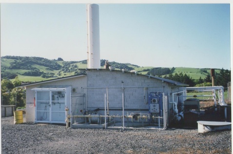
The compressor house circa 1998. The incoming lfg gas circuits are to the right of picture. After compressing and scrubbing, the gas is fed to the gas drier (the blue equipment at the near RH corner of the building). The gas is then ordorised with mercaptan injection (near centre of the building) before export to Dunedin via the high pressure pipeline (exiting underground to the left of the small odoriser tank). On the far left of the picture is the metering equipment. The scrubber tower is dominant - centre pix behind the compressor house.
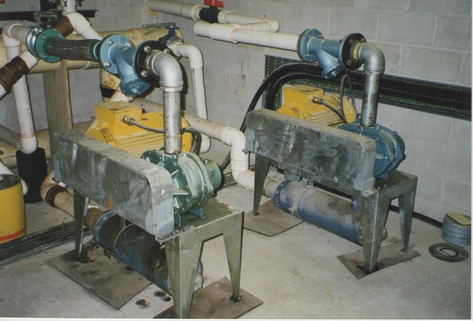
Two gas vacuum pumps were connected to the underground gas gathering matrix, provided to draw the gas from the field. The system was duplicated to allow for different conditions among the four "fields". Each pump was provided with a variable speed controller, and manually set as required. It was quite a balancing act to collect the maximum CH4 volume. Too little negative pressure allowed the gas to escape, while too much negative pressure allowed air to be drawn into the catchment system. It was noted natural CH4 production varied wildly between day and night, calm and windy, wet and dry, and cool and hot.
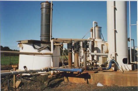
Overview of the scrubbing equipment. The tower on the right is the scrubbing tower, the centre tower is water regeneration and the black tower is water cooling. The three high-pressure pumps supply the water to the scrubber tower, while a fourth pump (obscured) recirculates the water in the two holding tanks. Clearly the water tank on the left has stability problems.
The Blower provides fresh air for the water cooling tower and also pressure to deliver the unwanted gases, removed in the scrubber tower, and recovered in the water regeneration tower, to the bio filter beds sited roughly directly behind the blower.
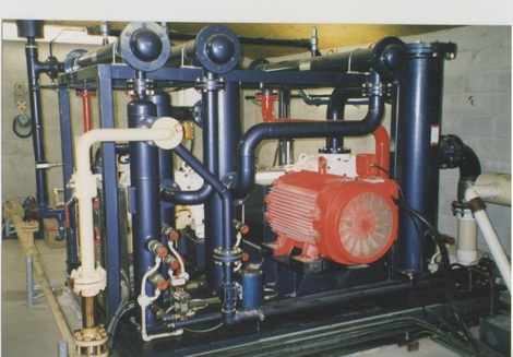
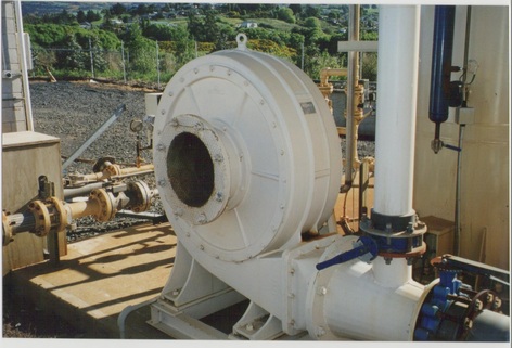
The gas compressor. This was, as they say today, a seriously cool machine. The low pressure input is at the right of picture, the high pressure output to the lower left. It was a pity it only had a short life span. The machine was not running when this photo was taken, but the control panel record shows the discharge pressure alarm/cut-off set at 300 PSI. Someone, I don't know who, got a real bargain when this machine was sold off.
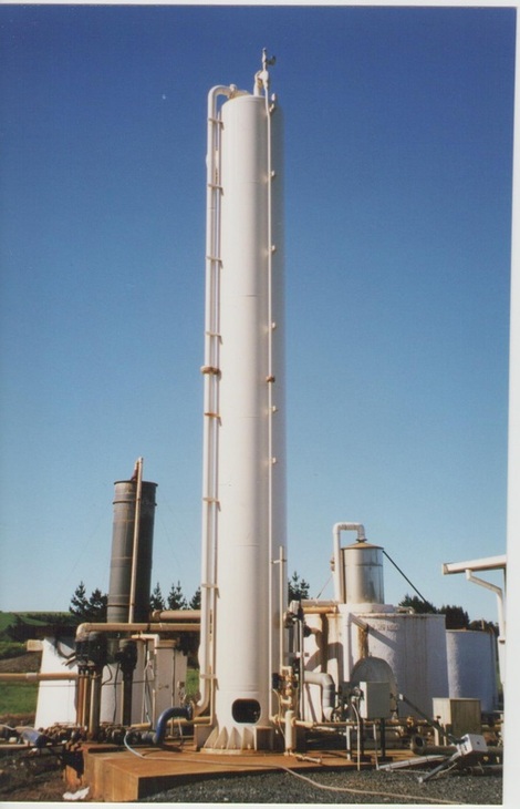
The scrubbing tower in detail. The larger pipe on the left hand side of the tower is the water in, while the smaller pipe on the right hand side is the scrubbed gas out. The raw gas inlet and the water outlet are not visible in the pix being on the far side of the tower. The working water level in the tower was maintained at approximately 2 meters by level sensors operating a motorised valve on the water outlet pipe.
Odoriser bulk tank. The Mercaptan was automatically injected into the gas stream as a safety feature. Methane, LPG and Town gas have little smell of their own, and would be difficult to detect in the event of a gas leak. The Mercaptan material has an extremely pungent and strong smell, familiar with gas uses, and often mistaken as "the smell of gas"
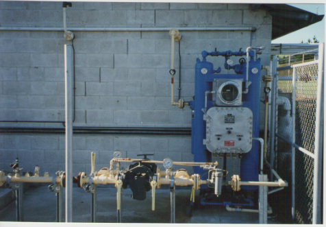
The gas drier. The drier was an automatic change-over device with two operational systems. When one unit was in service, the other side was automatically regenerated. The wet gas exited the scrubber tower on the far side of the building, was piped straight through to connect to the left hand side of the drier. Dry gas exited the right hand side of the drier and moved on to the odorising unit to the left.
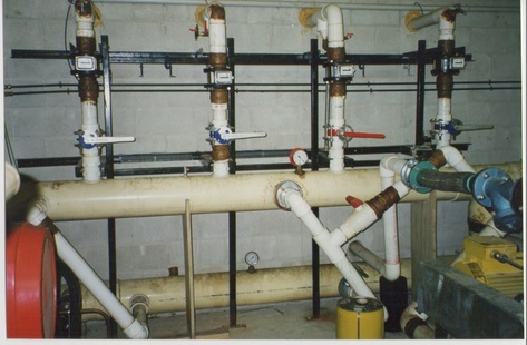
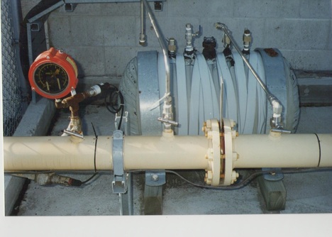
The inlet manifold. The main delivery pipes from the 4 gas fields were connected to a common manifold, with a relatively sophisticated by-pass arrangement, allowing the two field suction pumps to be connected to each field as required. To the left of the picture the manifold is connected to the inlet of the compressor.
