PAGE INDEX: 1. The Kensington Connection. 2. The HP connection 3. The Purifier connection. 4. The Steam connection. This page is work-in-progress - call back soon
1. The Kensington connection
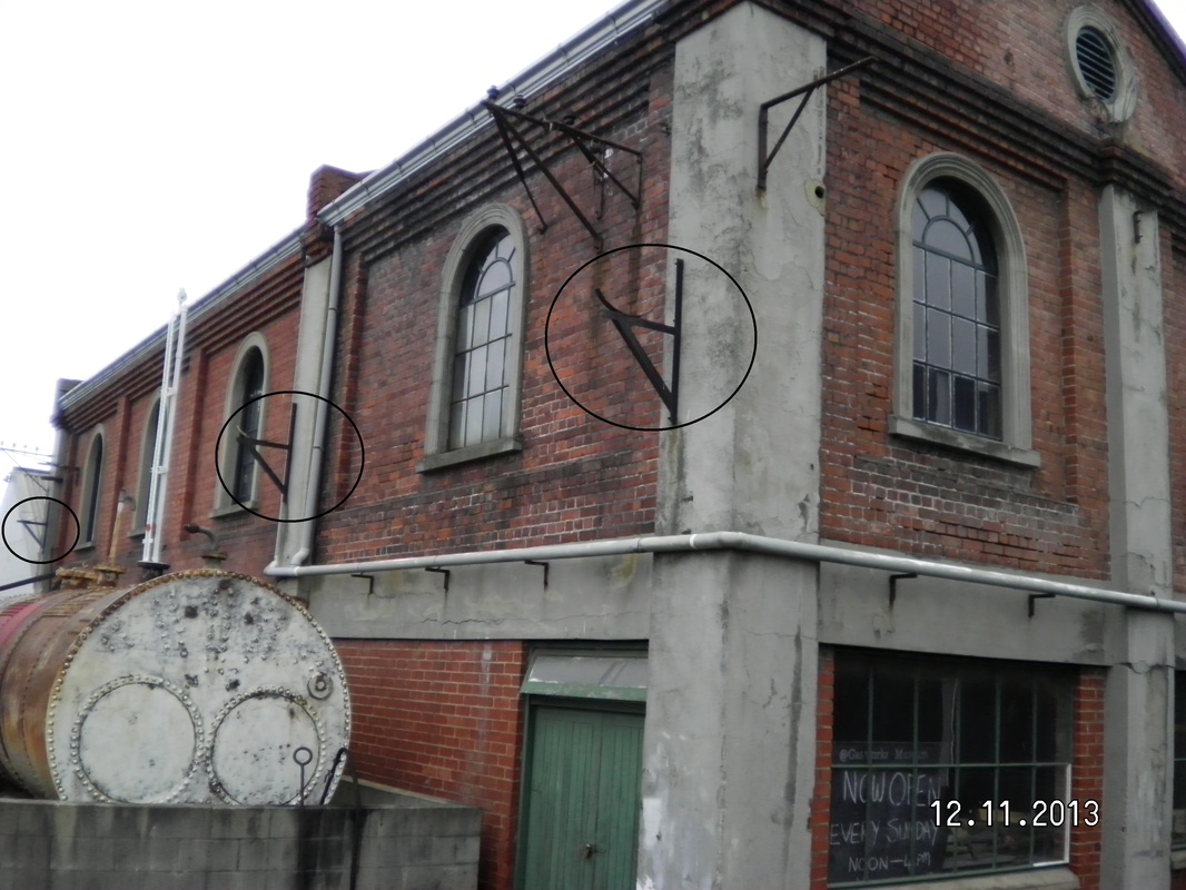
Brackets along the north side of the Anderson room supported this section of the Kensington main
|
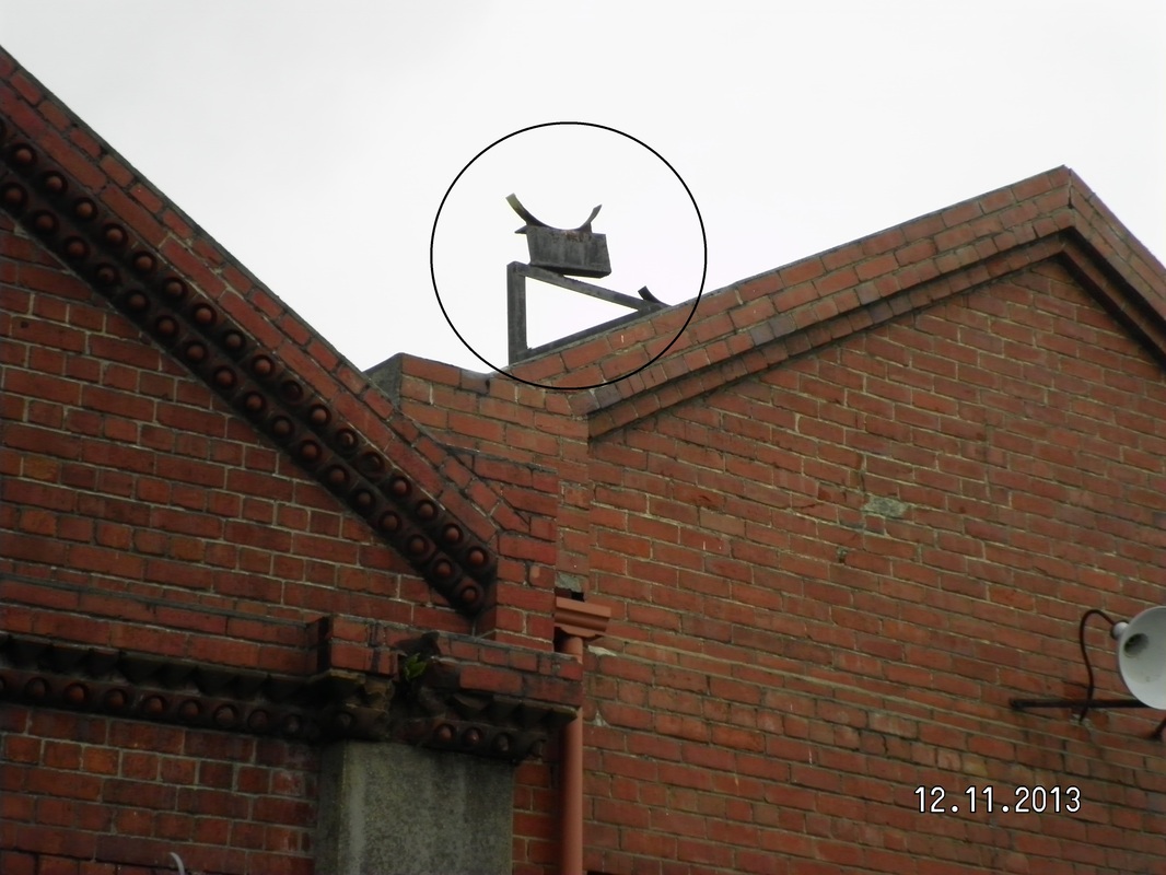
Support bracket on the Southern gable end of the over-roof section
|
Observers of the Gas works model or historic aerial photographs on display at the museum, cannot miss the bright yellow pipe shown between the centre of the complex and the SE corner. This is the “works” portion of the 1967 constructed, 18 inch main to the Kensington Gas Holder.
Originating from the common pipework connecting the coal gas and P3 gas production trains, the main pipe was routed behind the old retort house, overhead to the North wall of the Anderson room, above the roof of the Engine house, and overhead to the site SE corner boundary. (Sadly the pipe work has all gone, but some support structures remain, and these are recorded here). From the works boundary** the connection was to an underground 18 inch main along Braemar Street, Hillside road, across the now Pac-n-Save car park, Prince Albert Road
and Percy street to the Kensington Holder.
With the demise of coal gas production in 1987, the main was cut back at the Western end of Braemar street and redirected underground into the gas works site for connection to the MS plant and later the TLP and TLF gas plants. The main was in use until the demolition of the
Kensington Gas holder in 2000.
This main was dedicated exclusively to export and import of distribution-ready town gas from the works to Kensington, and as such was
configured for two-way flows. In coal gas days, the blowers pressurised the outgoing gas, while returning gas was fed by the gravity function of the holder. The Works blowers could also be run in reverse, therefore drawing gas from the holder. On return to Braemar street, the gas was directed into medium or high pressure mains, or to the low pressure network.
Thanks to Nova Gas and to my gas industry colleagues Colin and Ryan, for allowing me to access distribution network drawings and for sharing
memories of their early days at the gas works.
** This SE corner of the coal gas works is the only point of export from the (now) museum complex. All others, and there were many, were outside the current museum boundaries. Together with the Kensington connection, a 10 inch medium pressure main to Caversham also shared this site. (Originally a 10 inch connection to the Kensington Holder, but reconfigured on introduction of the 18 inch main, this medium pressure main to Caversham left from this point. Perhaps some future interpretation/indication/identification to mark this position would be appropriate. -Ed)
2. The High Pressure Connection. (6 psi)
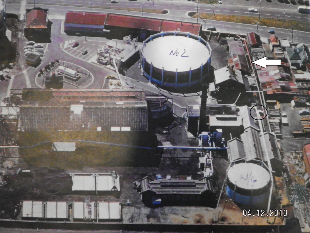
The compressors' input tee connection (circled) and the output (arrow) to Andersons Bay road.
|
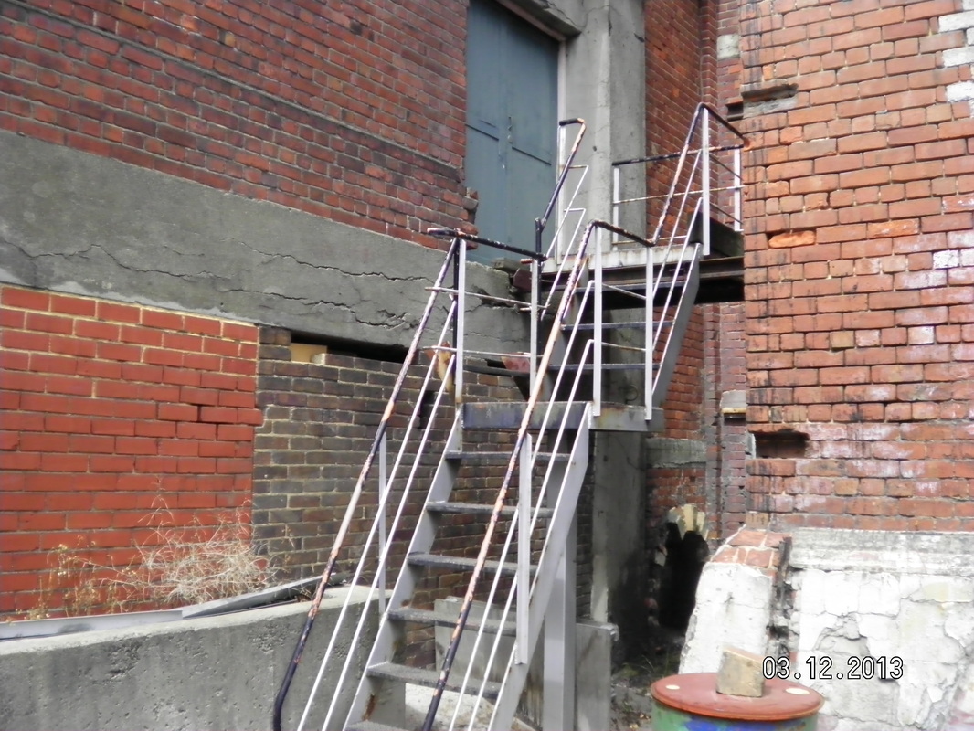
This stairway, originally providing access to the HP input tee, has been saved and relocated to the loft.
|
The mid 1960's saw the introduction of a “high pressure” network, supplied by electrically driven compressors fitted into the (now) long room and toilet/kitchen area of the museum. The input to the compressors was a controlled connection from the 18” main described in the
“Kensington Connection”. There were three valves installed in the elevated section of the main, near the NE end of the Engine house. The valves were manually operated and designated “A”, “B”, and “R”. Valves A and B were in-line on the main and R isolated the tee connection to the compressors. The valves were accessed by use of a steel stairway, now preserved at the museum, but relocated to provide access to the loft, the room above the dungeon. The output from the compressors was connected to a (then new) high pressure main installed along Andersons Bay road. Sadly, the compressors, the electric motors and control gear, and most of the pipe work and the valves have gone, with only the stairway remaining. A short pipe up-stand, (in the Eastern storage area – near the kitchen wall) remains, and was certainly part of this system, however, it is unclear if this was part of the compressor input or output circuits.
“Kensington Connection”. There were three valves installed in the elevated section of the main, near the NE end of the Engine house. The valves were manually operated and designated “A”, “B”, and “R”. Valves A and B were in-line on the main and R isolated the tee connection to the compressors. The valves were accessed by use of a steel stairway, now preserved at the museum, but relocated to provide access to the loft, the room above the dungeon. The output from the compressors was connected to a (then new) high pressure main installed along Andersons Bay road. Sadly, the compressors, the electric motors and control gear, and most of the pipe work and the valves have gone, with only the stairway remaining. A short pipe up-stand, (in the Eastern storage area – near the kitchen wall) remains, and was certainly part of this system, however, it is unclear if this was part of the compressor input or output circuits.
3. The purifier connection.
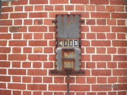
This is the sole remaining artefact from the purifier system. See text for the explanation.
The purifier connection. On the Braemar street end of the Fitting shop West wall remains the only remaining artefact from the coal gas purifier
systems. In the 1960's twelve purifier boxes were in service, generally operated in pairs. The process allowed for one pair in service, one pair ready for service, and the rest in regeneration mode. The purifiers consisted of “boxes” containing wood shavings and slag, and when selected, (a very basic description): the hydrogen sulphide and hydrogen cyanide remaining in the scrubbed coal gas was removed by reaction with the slag to produce various calcium and ferrous sulphides, sulphur and water. The gas purifier inlet pressure was monitored, and with an increased pressure due to accumulating solids, the pair were taken out of service for regeneration, and an alternate purifier pair selected. The change-over was achieved by selection of appropriately placed valves, and operators were advised of the required configuration by a manually controlled indicator – our remaining artefact. Two valves were operated, and the correct sequence enunciated on the indicator. In the picture the two valves to be selected would be Valve 41 and valve 23.
systems. In the 1960's twelve purifier boxes were in service, generally operated in pairs. The process allowed for one pair in service, one pair ready for service, and the rest in regeneration mode. The purifiers consisted of “boxes” containing wood shavings and slag, and when selected, (a very basic description): the hydrogen sulphide and hydrogen cyanide remaining in the scrubbed coal gas was removed by reaction with the slag to produce various calcium and ferrous sulphides, sulphur and water. The gas purifier inlet pressure was monitored, and with an increased pressure due to accumulating solids, the pair were taken out of service for regeneration, and an alternate purifier pair selected. The change-over was achieved by selection of appropriately placed valves, and operators were advised of the required configuration by a manually controlled indicator – our remaining artefact. Two valves were operated, and the correct sequence enunciated on the indicator. In the picture the two valves to be selected would be Valve 41 and valve 23.
4. The Steam Connection
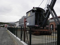
One of two steam pipe supports remaining upright near the Braemar street fence. A third support is stored with the spare gas holder legs.
|
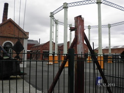
From here the pipe ran overhead to a water gas holder leg and on to the engine house.
|
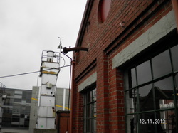
This pipe stub was the Engine house steam pipe connection from the Woodall-Duckham retort. Today the museum utilises the remaining indoor section of the pipe to provide steam connections to the operational exhausters and the beam engine. The small pipe leading down from the flange connects to an in-use steam trap and manual drain valve. (the near horizontal feature is the overhead electrical connection from the Fitting Shop)
In addition to the oil-fired museum
donated boiler, the boiler house and Anderson room contain two
original works boilers, both awaiting some presentation attention.
Connections between all three remain today with the still-in-use
steam manifold. Steam was utilised during the vertical retort
gas-producing process, and a waste heat boiler was installed as an
integral part of the Woodall-Duckham retort machinery. At times,
retort steam excess to the then requirements, was available and this
was piped to the Engine house for use in other parts of the works.
The pipework was configured for one-way operation and there is no
current evidence of boiler house steam being returned to the retort.
Like much of the plant sadly this fourth steam connection has gone,
but we are left with some support structures and the boiler house
stub, today modified with a steam trap and a manual condensed water
drain. The pipe ran from the Woodall-Duckham retort, along the works
Braemar street boundary, across to a watergas holder leg, on to the
South wall of the engine house, and internally to the boiler house.
The pictures record the remaining support structures and the engine house connection.
The pictures record the remaining support structures and the engine house connection.
