The Dunedin Gasworks museum Engine collection
(all the engines described here are regularly steamed)
This page contains multiple records - scroll down to see the latest
Page Index: 1. Beam Engine 2. The Donkin 3. No 2 Exhauster 4. The Reader 5. The electric Donkin 6. The little Exhauster 7. Reader maintenance
1. Beam Engine 1868


The beam engine.
1868
We believe our beam engine is the oldest operating steam engine in New Zealand. A North Island collector quotes one of his collection as the oldest, dated 1869. However, as recorded here, we have date verification for our machine.
The engine is on loan to the Gasworks museum from Toitu OESM, and their records indicate and confirm that it was given to the Early Settlers Museum in August 1927 from the City Gas Department via Mr J B Shacklock (Mayor of Dunedin in 1914, city councillor 1905-13 and 1914-35, chairman of the electricity committee for many years). The OESA Minutes record the gift as “Gas Dept. per J.B. Shacklock, old beam engine first used in Dunedin gas works.”
Gas works Museum volunteers retrieved most parts of the engine from two different storage areas of the ESM in the late 1900's and with great skill and good engineering practice brought the machine to working order. Missing from the collection of parts was the piston, and a new cast iron piston was fabricated. Having a similar cylinder bore to a DE class locomotive engine, piston rings were acquired from a helpful railway source.
The machine operates at 40 psi, and is connected to the museum steam reticulation system through an in-line pressure reducer. The machine is manually lubricated, and trained volunteer operators are always on-site during public open and other steam-up days. Running without load, and “ticking over” at around 100 rpm. The machine requires or demands little maintenance.
2. The Donkin 1926


The Donkin is a
horizontal, steam driven, duplex, reciprocating compressor. Installed
in 1926, it is rated at 100,000 cuft/hour of gas at 5 lbs/sqin.
Research, using old schematic diagrams indicates the machine was
primarily used to supply the (then) HP network at 2lbs/sqin. Later in
1964, a new 6lb/sqin, HP main was installed, supplied by electric
driven compressors, and the old system was re-designated as the
medium pressure network.
The machine could also be configured to transfer gas between gas holders.
Today, the engine has the steam and exhaust connections to one steam cylinder disconnected, leaving one half of the duplex compressor driven through the “lazy” cylinder. The story passed down is that during 1962 new regulations were introduced requiring advanced operator qualifications for machines of higher horse power. As the Donkin fell into the category of operators being required to hold a first class steam ticket, and, the highest qualification of existing staff being a second class ticket, at the time, it was determined to be expedient to reduce the machine power rather than train or employ qualified staff.
3. No2 Exhauster

Work in progress - call back later
4. The Reader

work in progress - call back later
5. The electric Donkin 1917


This machine is a Donkin
vane pump type exhauster driven through a Power Plant Co, 60 HP reduction gear box by a BTH 60 HP, 500 volt dc
motor. In turn the motor is supplied by a motor-generator set, nearby
in the engine house. The MG set is a General Electric induction motor, rated 50 HP, with a 2 hour, 25% overload rating. The generator is a General Electric 50 HP DC machine.
Research has so far has not returned an actual installation date for the exhauster, but as the gear box name plate is stamped 1917, it can be assumed around 1918. Old schematic diagrams indicate the machine was primarily used to supply the (then) HP network at 2lbs/sqin, preceding the 1926 Donkin reciprocating compressor.
Installed in the original section of the engine house, set apart some distance from the motor/gen set, and with a time line not associated with other retort developments, it is likely the machine was added specifically as additional network support.
From the report: Plant history of Dunedin City Council gasworks Hillside road site 1863 – 1997, by Peter Robinson 2 July 1997.
"The motor generator installed in 1920 – 1921."
Editors Note: Peter Robinson's report makes no mention of the electric driven Donkin exhauster so it could be assumed this was already on site and the machine's gear-box date stamp of 1917 fits with this. Therefore, it is possible the steam engine driven generator (long gone, but visible in photographs) was installed around this time, and for a short time, supplied the electric driven exhauster. This theory could also perhaps explain why the motor/gen set is installed a significant distance from its load.
The machine and the motor-gen set are presented for static display only, as while most of the associated switchgear has been retained, effectively all the cabling has been removed. Further, connection to the electricity network would result in an unsustainable increase in Museum capital and running costs.
6. The little exhauster 1909


The small exhauster is
the sole remaining unit of an original pair, installed in 1909. The
machine consists of a single steam engine driving a vane pump, and
was used to draw raw gas from the various retorts. This engine is
unique to the museum as it is the only unit provided with variable
cutoff, an unusual feature with stationary engines, but common with
railway steam locomotives. The provision of variable cutoff allows
for maximum torque on start up, but at the expense of efficiency.
Our machine is, arguably, the best presented unit in our collection. During a lull in its working lifetime operation, the machine was allowed to rest, and the regular “turning over” routine was neglected. This resulted in an accumulation of tar in the vane pump, and the subsequent ceasing of the pump. In an (successful) effort to get the machine running, various products such as creosote and kerosene were introduced to the pump, but the inevitable spillage resulted in serious damage to the vane pump paint work. On commencement of the museum operations, early volunteers cleaned down the pump, repainted in the original colours and restored the fancy scroll work decoration.
Situated in the original (middle) section of the engine house, this machine and its pair were likely installed in conjunction with the new horizontal retort of 1909. Old schematic diagrams support this theory, as do Museum interpretation prepared by others. This however is at odds with presented papers indicating the machine was installed in conjunction with the 1928 Glover-West retort.
6 July 2014. After having been shut down for 15 months, and now having steam available due to boiler testing, today, 6 July 2014, we took the opportunity to run 3 of the museum engines.
https://www.youtube.com/watch?v=npoFPvDDzL0
https://www.youtube.com/watch?v=uFoKtLmTS4c
https://www.youtube.com/watch?v=npoFPvDDzL0
https://www.youtube.com/watch?v=npoFPvDDzL0
https://www.youtube.com/watch?v=uFoKtLmTS4c
https://www.youtube.com/watch?v=npoFPvDDzL0
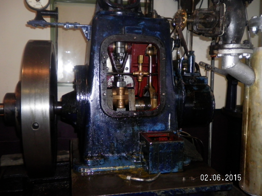
7. Reader Maintenance
June 2015, Tom removed the crankcase cover and completed a routine oil change and filter maintenance. He reports " it was due"